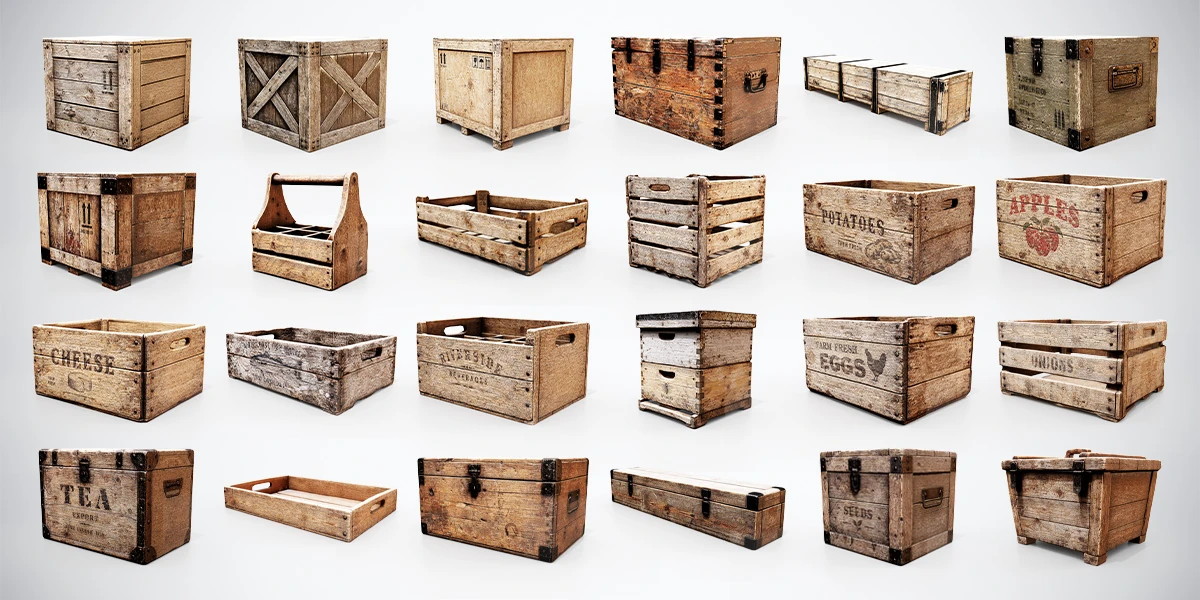
An open crate needs hollow collision when another object must enter it. A single Box Collider around the outside may block the opening even though the rendered container is empty. This tutorial builds a floor and four walls, then checks whether small objects can enter, settle and remain inside.
The example uses Unity 3D physics and a simple rectangular container. For the broader choice between primitive, compound and mesh collision, start with the game-prop collider guide. Here, the task is narrower: preserve one usable opening and make the resulting setup reusable.
Choose an open container and define the contact test
The 24 Wooden Crates & Boxes bundle includes open containers and trays alongside its closed boxes and chests. Select an open shape for this exercise. The closed lids are fixed, and the models are supplied as static props without rigging or animation. Collision and optional physics behavior are setup you add to your project.
Decide what needs to fit inside. A decorative container seen at a distance may not need interior collision. A crate that receives small physics objects does. Write the requirement in a testable sentence: “A small cube can fall through the opening and rest on the floor without escaping through a corner.”
Keep the first test simple. Use a plain cube as the dropped object instead of starting with an irregular tool whose own collider could confuse the result. Choose a size that clearly fits the opening, with room around it.
Prepare a root with predictable coordinates
Complete the Unity model import checks before fitting collision. Confirm the model’s dimensions and orientation, then create an empty prefab root named Crate_Open_Static. Put the visible model under that root and keep collision children separate from the render object.
For the worked example, the root sits at the center of the container’s outside bottom. X runs across its width, Y points upward and Z runs along its depth. Keep the root and collision children’s scale at one and their rotations at zero while entering the values below. Position the visual child to match that coordinate convention.
These are training dimensions, not measurements of a specific product model. The example container has an outside width of 1.00, height of 0.60 and depth of 0.80 Unity units. Its floor and walls are 0.05 units thick. Replace these dimensions with ones appropriate to your actual mesh after the basic setup works.
If the visible model’s pivot makes this alignment confusing, use the origin and pivot workflow to resolve the hierarchy. Keep the intended contact surfaces and coordinate reference clear before adjusting physics settings.
Build the floor and four walls
Create five children under the root and add one Box Collider to each. Leave each child’s local position at zero and enter the offsets in its collider’s Center field. Alternatively, you can position the child and leave its collider centered, but do not apply the same offset in both places.
The following values use X, Y, Z order. Size is the collider’s full dimension along each axis, not its half-width. Unity’s Box Collider reference describes the Center, Size and Edit Collider controls.
| Collision child | Size: X, Y, Z | Center: X, Y, Z |
|---|---|---|
| Floor | 1.00, 0.05, 0.80 | 0, 0.025, 0 |
| Left | 0.05, 0.55, 0.80 | -0.475, 0.325, 0 |
| Right | 0.05, 0.55, 0.80 | 0.475, 0.325, 0 |
| Front | 0.90, 0.55, 0.05 | 0, 0.325, -0.375 |
| Back | 0.90, 0.55, 0.05 | 0, 0.325, 0.375 |
The floor occupies Y = 0 to 0.05. The walls begin at its top and end at Y = 0.60, which makes their height 0.55 and their center height 0.325. The front and back walls fit between the left and right walls, so their width is 0.90.
This leaves an interior width of 0.90 and depth of 0.70, with the supporting floor surface at Y = 0.05. Inspect these relationships in the Scene view. There should be no sixth box spanning the open top or filling the empty middle.
Adapt the example to the actual crate
Place the five shapes against the visible mesh and inspect them from above and from both side directions. Align the floor with the surface on which contents should rest, then fit the wall boundaries around the usable interior.
Real models may have sloping sides, uneven boards, a thick rim or a shallow base. The numerical example does not automatically fit those shapes. Decide which details change the required contact and adjust the representation accordingly. A decorative board gap does not necessarily need to be an escape route for small objects.
Check the smallest object that must stay inside. A visible opening between boards and a collision opening serve different purposes; preserve a gap only when gameplay needs it. If the shape becomes too irregular for five boxes, use the same contact requirement to decide where another primitive is justified.
Keep Is Trigger off for these physical surfaces. Also inspect the imported hierarchy for an extra enabled collider that encloses the whole mesh. That hidden solid shape can block the opening even when the five new children are fitted correctly.
Keep the container static or give it one Rigidbody
Start with a stationary crate and no Rigidbody on its hierarchy. Give the dropped test object a solid collider and a dynamic Rigidbody. This isolates the interior contact test from the additional movement of the container.
If the game needs the crate itself to move under physics, create a separate prefab variant and add one Rigidbody to its root. Keep the five collider children under that body, without separate child Rigidbodies. Unity’s compound collider instructions describe this arrangement.
Retest after making the container dynamic. A working stationary receptacle does not prove that a moving, stacked or carried container behaves as intended. Mass, friction, movement logic and the other objects in the scene are project decisions rather than values supplied by this example.
Do not replace the hollow arrangement with a single convex Mesh Collider just to reduce the number of components. A convex hull can span the opening and remove the interior space you need. The Mesh Collider documentation explains its convex representation and Rigidbody constraints.
Test the opening, floor and corners separately
Run a small acceptance scene with a ground plane, the crate and the test cube. Begin with gentle drops from just above the opening so high-speed collision behavior does not obscure basic fitting problems.
- Drop the cube near the center. It should enter and rest on the visible floor.
- Repeat near each side. Check for invisible surfaces that stop it above the opening.
- Repeat near all four interior corners. Inspect the collider boundaries if it escapes through a seam.
- Place an object wider than the opening across the rim. It should not be expected to fit inside.
- For the dynamic variant, repeat the intended handling and stacking behavior with the crate free to move.
If an object falls through the base, check whether the floor collider is enabled, solid and on an interacting physics layer before making it thicker. If it floats above the floor, inspect collision bounds on both the crate and the dropped object. If it starts shaking, check for initial intersections before increasing geometry detail.
Fast throws are a separate acceptance case. Once basic contact works, test the game’s actual speeds and investigate movement and collision-detection settings if needed. Passing a gentle drop test alone is not evidence that every high-speed interaction is supported.
Save and measure the finished prefab
Save the configuration using the Unity prefab workflow, then place a fresh instance in the test scene. Repeat the center and corner checks to catch settings that existed only as scene overrides.
Record the container’s intended role, its usable interior and the smallest contents you tested. If it also needs a proximity trigger or interaction script, keep that setup clearly separate from the five physical surfaces. An opening container animation is additional work, not a consequence of adding colliders.
Use the Physics Profiler when many copies appear in the target scene. Compare the same object count and interactions when considering a different representation. The purpose of this five-shape example is to preserve useful empty space; its actual runtime cost must be measured in your project.