
Learn how to create detailed mechanical parts, build reusable kitbash libraries, and speed up your sci-fi and industrial modeling workflow.
Hard surface modeling in Blender becomes easier when you separate the main shape, the cuts and the finishing work. Mirror helps maintain symmetry, Boolean creates openings and intersections, and kitbashing lets you reuse well-designed components. The goal is an object that reads clearly and remains easy to revise.
This guide follows a small mechanical mounting bracket from blockout to reusable asset. You should already be comfortable selecting objects, switching between Object and Edit Mode, and moving geometry. The same decisions apply to a robot joint, an equipment housing or a sci-fi vehicle panel.
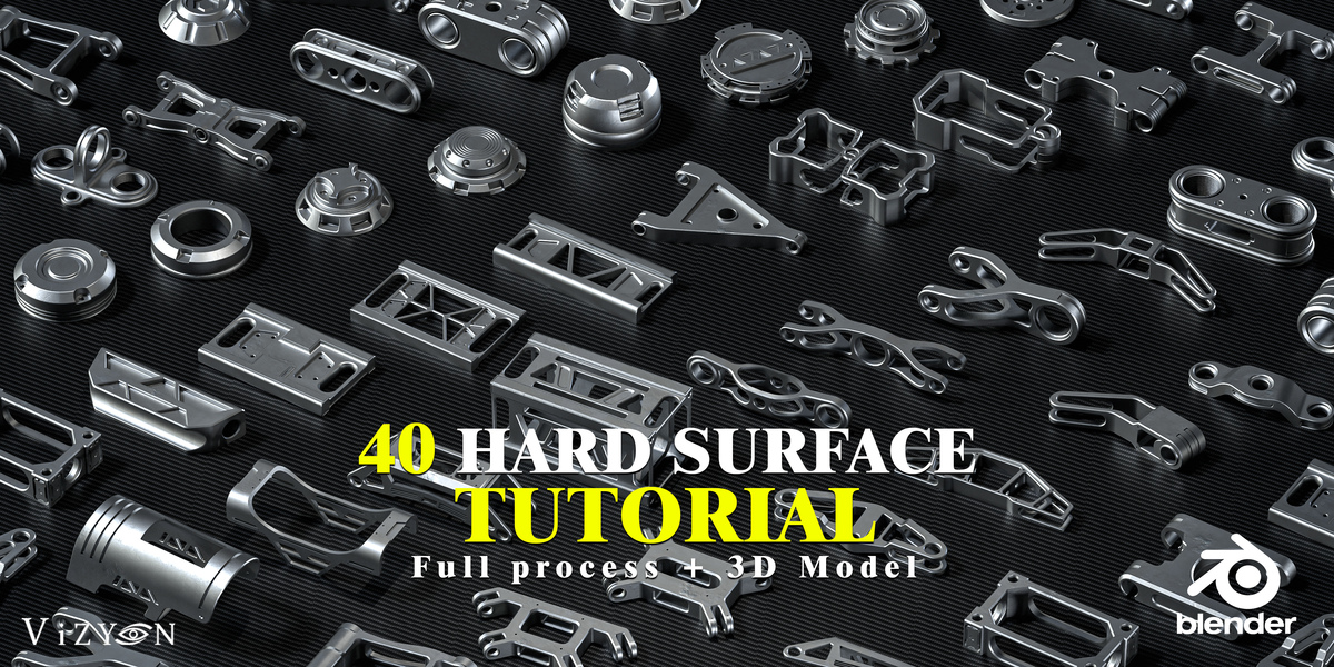
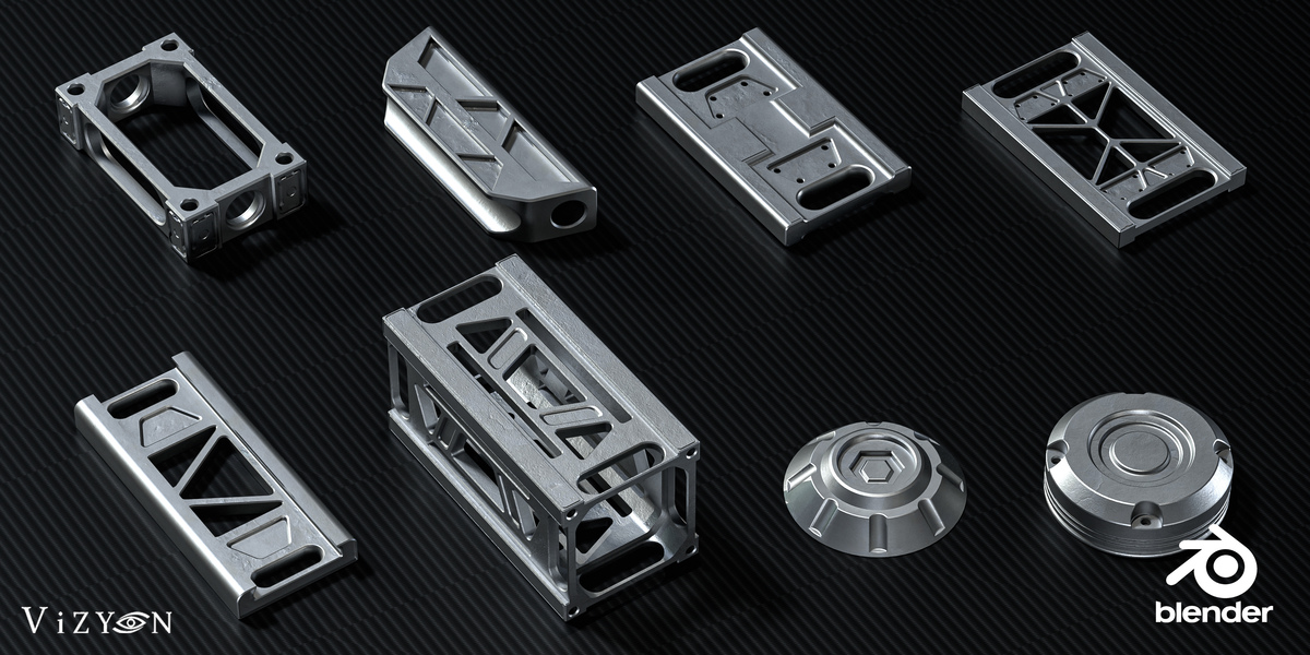
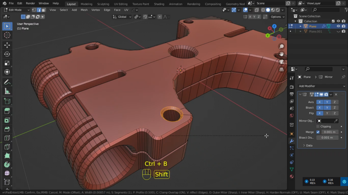
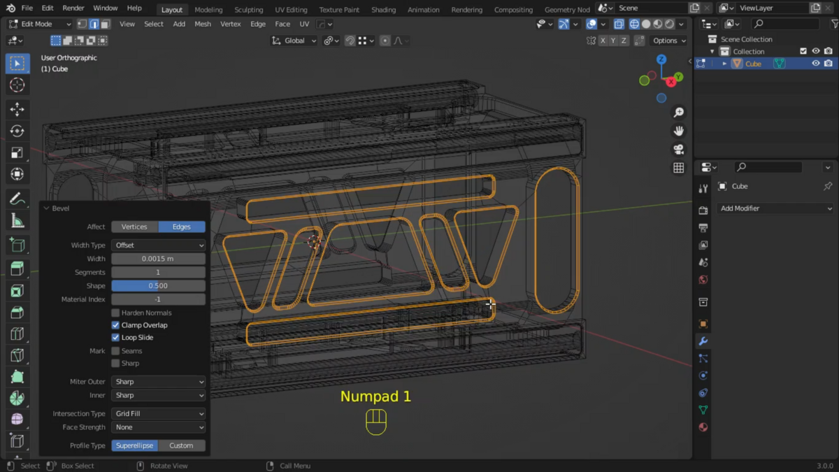
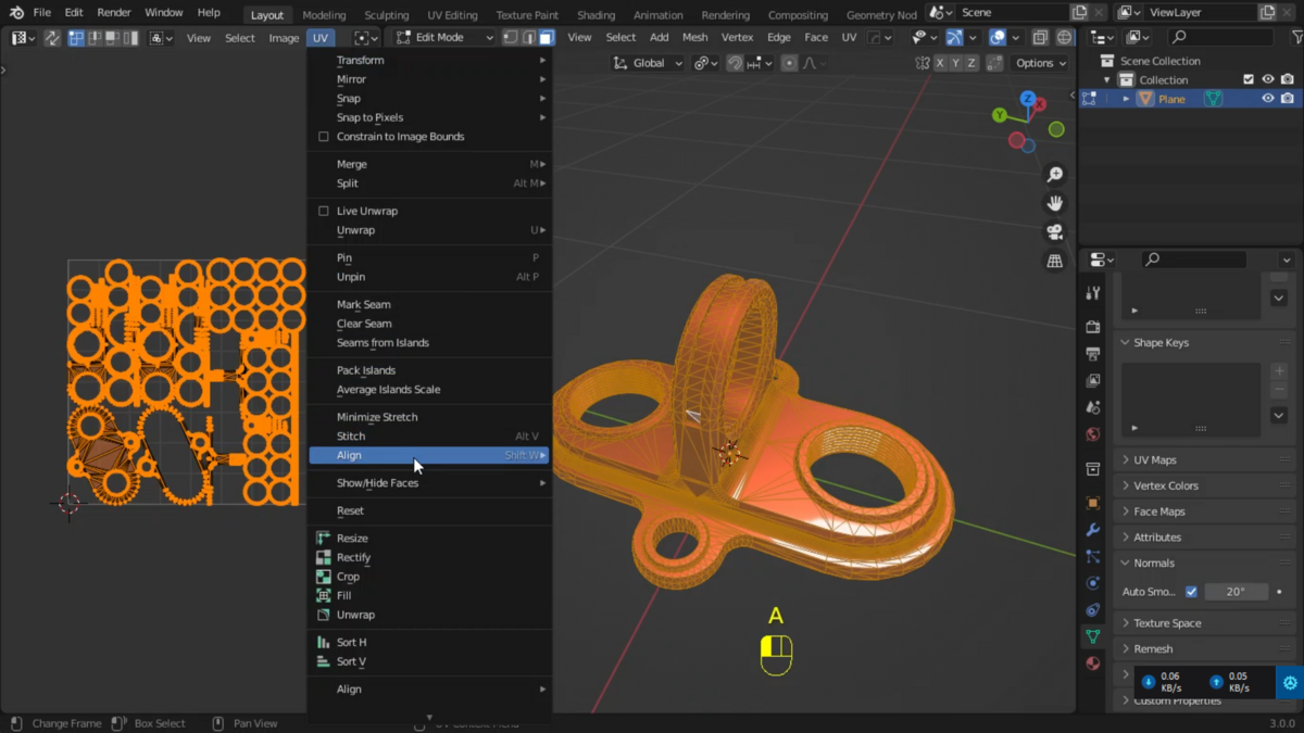
For structured practice, 40 Hard Surface Kitbash / Full Tutorial + 3D Model by Vizyon Designers is a relevant companion. Its focus on Boolean and Mirror fits the workflow below. The product renders and tutorial screenshots reproduced here are credited to Vizyon Designers; they illustrate the product, rather than the result of our bracket exercise.
Affiliate disclosure: This article contains affiliate links. I may earn a commission if you purchase through them.
If you learn best by watching a modeling process, explore the hard surface tutorial and kitbash pack on Superhive. Check the selected variant: some options contain models or tutorials separately.
Start with function, silhouette and scale#
Before cutting holes, decide what the part does. A bracket needs a mounting surface, space for fasteners and enough material around its openings to look credible. A protective housing needs an interior volume and a plausible way to attach or remove its cover. These are visual design questions, not an engineering certification.
For the exercise, use a rectangular plate 120 mm long, 60 mm wide and 8 mm thick, with a central opening and two mirrored mounting holes. These dimensions are an illustrative modeling brief. They are not manufacturing specifications. Set units to Metric and use Blender’s dimension fields to establish the size.
Judge the silhouette in front, side and perspective views. Keep three levels of detail distinct: the plate is the primary form, its opening and mounting holes are secondary forms, and shallow recesses or edge treatments are tertiary details. If the primary form feels weak, more screws will not solve it.
Create separate collections for the body, cutters and reference objects. Give objects useful names such as Bracket_Body and Cut_MountHole. Apply non-uniform object scale before tuning dimensional operations; when starting fresh, scaling mesh vertices in Edit Mode also keeps object scale at one.
Build symmetry with the Mirror modifier#
Place the object’s origin at the intended center of symmetry. For this bracket, keep the origin at the plate’s center, cut the mesh along its local X centerline, remove one half and remove any face capping the center seam. Add Mirror on X. The generated half should meet the original without an internal wall.
Mirror uses the object’s local axes and origin unless you supply a Mirror Object. An Empty is useful when the symmetry plane needs to be positioned independently. Check that plane before adjusting vertices to compensate for an apparently offset result.
Enable Merge to join matching vertices within a small distance, and Clipping to keep seam vertices from being dragged through the plane while editing. These controls have different jobs. If the seam stays open, align its vertices with the plane and inspect the merge distance; a large tolerance can collapse nearby details.
This distinction is documented in Blender’s Mirror modifier reference. Start with one axis for the exercise. Add a second only when the design genuinely has that symmetry.
Use Boolean operations for purposeful cuts#
A Boolean combines the volumes of the body and an operand, often called a cutter. Put the modifier on the body and assign the cutter object. The three operations solve different problems:
| Operation | Effect | Mechanical use |
|---|---|---|
| Difference | Removes the cutter’s volume from the body | Mounting holes, slots and recesses |
| Union | Combines the overlapping volumes | Joining a boss or lug to a body |
| Intersect | Keeps the shared volume | Trimming a component to a boundary |
Use closed, consistently oriented meshes for predictable results. Extend a through-hole cutter beyond both sides of the plate, avoiding faces that merely touch. The Exact solver is a useful option when overlapping geometry causes problems, though it can cost more evaluation time. Blender’s Boolean reference explains the solver differences; available names depend on your version.
Keep cutter meshes simple while establishing placement. A cylinder needs enough sides for its visible outline, but an unnecessarily dense cylinder makes every resulting hole harder to edit. Set cutters to a wire or bounds viewport display for visibility, and disable their render visibility while retaining them as modifier operands.
Cut the bracket in a controlled order#
- Add a rounded rectangular cutter for the central opening. Center it on the plate and leave a generous border on all sides.
- Add a cylinder perpendicular to the plate for one mounting hole. Position it clear of both the outer edge and the central opening.
- Create a matching cylinder on the opposite side. For this simple exercise, two named cutter objects are easy to inspect and revise.
- Add Difference modifiers to the body for the central opening and each hole. Move one cutter slightly and check that the result updates cleanly.
- Make the body visible without its cutters and inspect both faces. An opening that looks correct from above can still leave an unwanted thin wall underneath.
Use Mirror → Boolean cuts → Bevel as a starting stack for this exercise. Mirror first closes the body; the cuts then act on the whole plate. The paired cutters must therefore be positioned explicitly: Mirror on the body does not automatically mirror a separate cutter object.
There is no universal stack order. Cutting a closed base before mirroring can repeat the cut with the base geometry; cutting afterward can produce unique details across the finished shape. Compare the evaluated result at each stage. The non-destructive modifier guide develops this way of thinking about dependencies.
Finish edges with controlled bevels#
A bevel creates the narrow surfaces that catch highlights around a manufactured edge. For the example plate, try a small width relative to its 8 mm thickness, then judge it at the intended camera distance. A bevel that consumes most of the border changes the design instead of simply finishing it.
Place the finishing bevel after the cuts if you want their new edges softened too. Start with a few segments and inspect the result before increasing them. Use an angle limit, weights or a vertex group when only selected edges should receive the treatment. The Bevel modifier documentation explains these controls.
If the width becomes unexpectedly tiny, inspect short edges and close intersections. Clamp Overlap can limit the bevel to avoid collisions; disabling it without inspecting the mesh may simply hide one problem behind another. Move the cut, simplify an unnecessary edge or use a narrower local treatment before adding more geometry.
The guide to mastering bevels helps distinguish shape-defining chamfers from small highlight edges. Keep an editable master before applying modifiers or performing manual cleanup.
Inspect topology and shading separately#
A clean highlight does not prove that a mesh is suitable for every destination. Conversely, a planar face with more than four sides is not automatically a modeling failure. Evaluate the topology against what happens next: a static product render, subdivision, deformation, a normal-map bake or a game-engine export.
Inspect large flat regions under a moving highlight. Look for dents, unexpected diagonal shading and narrow sliver faces near cuts. Then inspect the wireframe and face orientation. Smooth shading changes the interpolation of normals; it does not repair overlapping faces or insufficient curvature.
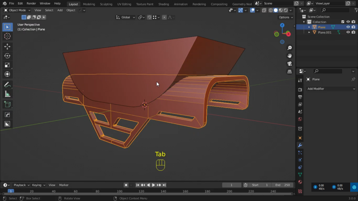
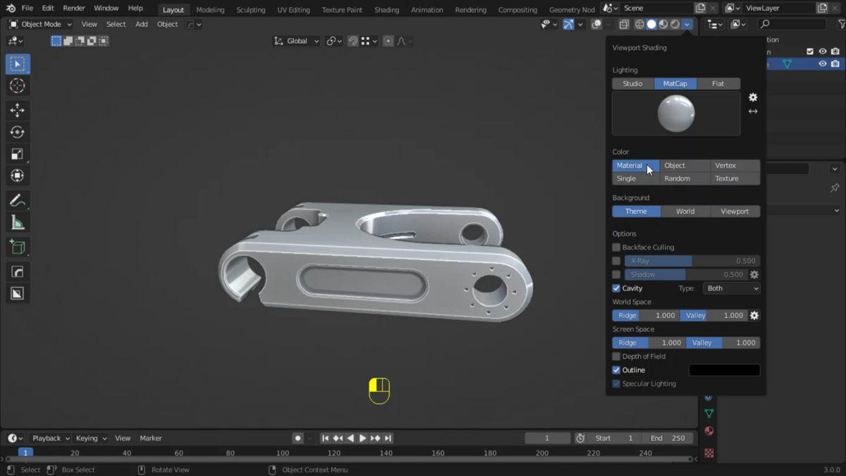
Use a neutral MatCap for fast shape inspection, then test with real scene lights and a simple material. The supplied screenshot below is a viewport preview, not a final lighting setup. It also shows an older Blender interface, so some labels differ in newer releases.
For a subdivided or deforming part, plan the edge flow deliberately. For a static triangulated export, inspect the actual triangulation rather than assuming the viewport’s implicit result will always match another application. The clean topology guide explains why the intended use matters more than a blanket all-quad rule.
| Symptom | First check | Useful next action |
|---|---|---|
| Boolean removes the wrong region | Operation, operand and face orientation | Test one simple cutter with other cuts disabled |
| Mirror seam remains visible | Origin, seam coordinates and internal faces | Align the seam and remove duplicate center faces |
| Bevel shrinks or pinches | Short edges, scale and neighboring cuts | Create more clearance or simplify the local shape |
| A flat panel looks dented | Face planarity and shading around cuts | Inspect normals and split or rebuild the affected region |
| Viewport becomes slow | Cutter density and long modifier stacks | Disable finishing modifiers temporarily while shaping |
Prepare UVs and a delivery mesh#
UV work becomes easier after the proportions and main cuts have stabilized. For the bracket, separate the broad front and back faces from the thin perimeter where that produces manageable islands. For cylindrical holes, consider a longitudinal seam so the interior can unfold as a strip. Check the result with a checker texture, especially around rounded openings.
Keep comparable visible surfaces at a consistent texture density. Leave padding appropriate to the target resolution and mipmapping requirements. An automatic unwrap can be a starting layout, but it still needs inspection for stretching, excessive island fragmentation and wasted space.
Make a delivery copy before destructive optimization. Retain the original body and cutters in the source project. For real-time use, inspect silhouette needs, hidden geometry, material slots and the final triangle count at the intended viewing distance. Bake small details when they do not justify geometry; the high-poly to low-poly workflow provides a fuller production path.
A visually detailed kitbash part is not automatically game-ready. Test its export, shading and UVs in the destination application before distributing it through a scene.
Build a reusable mechanical kitbash library#
Turn the finished bracket into a small family: a solid mounting plate, a frame with a large opening and a curved protective shell. Each should have a distinct silhouette and a clear attachment point. Several purposeful pieces are more useful than dozens of nearly identical variations.
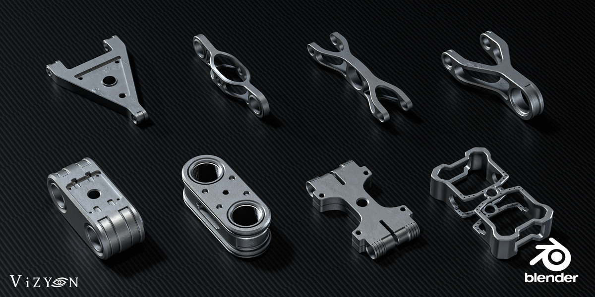
Use a consistent naming pattern such as Mech_Bracket_Open_01. Put origins where placement makes sense: the mounting plane for a plate, the rotation center for a hinge or the base of a housing. Test snapping each component to a simple assembly. An awkward origin costs time every time the asset is reused; the origins and pivots guide covers practical placement choices.
Save the library’s blend files in a dedicated folder and add that folder under Blender’s Asset Libraries preferences. Mark the intended object or collection as an asset, then organize it into catalogs such as Brackets, Frames and Housings. Save the file so the asset is available outside the current session. Blender’s asset library introduction describes this file-based workflow.
Keep editable construction projects separate from clean placement assets. If an asset depends on external cutters, include those dependencies intentionally or prepare an evaluated placement copy. Test it in a fresh scene: missing operands are easier to catch there than in the original file where everything already exists.
Kitbash a coherent sci-fi or industrial assembly#
Choose a main mass before adding parts. For a small sci-fi equipment module, use a simple housing as the dominant shape, two brackets to suggest mounting, and one recessed panel for access. Leave quiet surfaces between detail groups so the viewer can understand the construction.
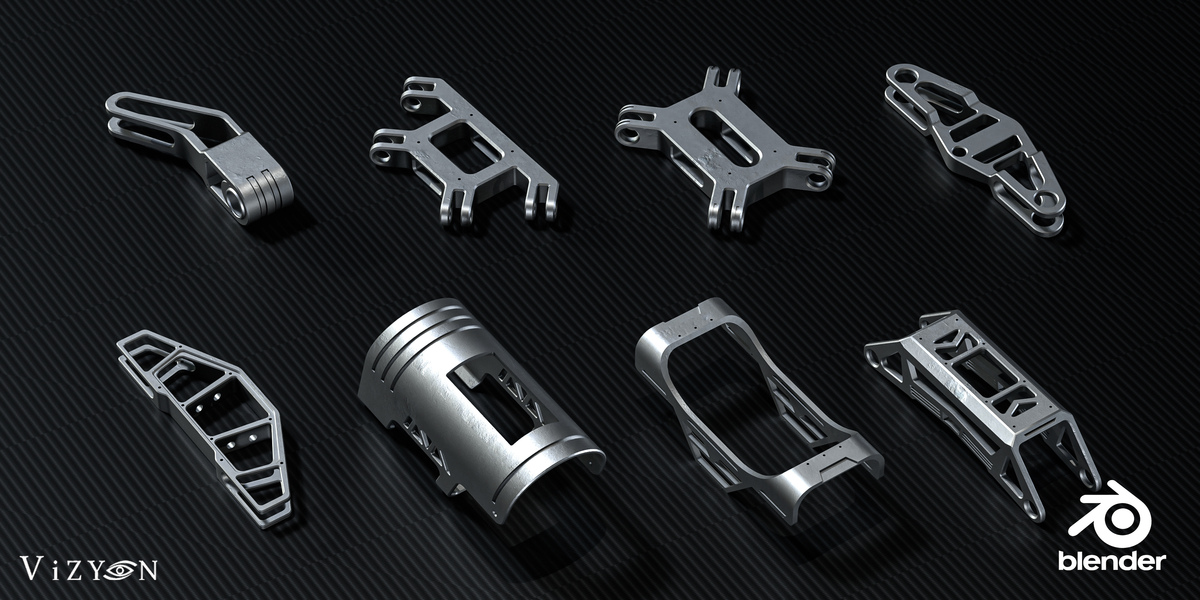
Keep repeated hole sizes, bevel character and panel thickness visually related. Attach components where they could plausibly connect. Avoid floating details, accidental intersections and decorative vents that cut through an obvious mounting point. Rotate a component to suit its function rather than scattering pieces randomly.
Change silhouette and arrangement before surface wear. The prop reuse workflow is useful when several assemblies start looking identical. A different bracket spacing or cover profile often contributes more than another texture variation.
For presentation, light the large forms first and then check whether the bevel highlights support them. A broad light source can reveal waviness that a busy environment hides. Use the metal object lighting guide when moving from modeling inspection to a polished product render.
When the Vizyon Designers tutorial is useful#
According to the product listing, the tutorial contains 40 parts and 13 hours 33 minutes of real-time recordings, using native Blender tools with an emphasis on Boolean and Mirror. The videos show shortcuts but have no narration, and basic Blender knowledge is recommended.
The listed model files include Blend, FBX and OBJ, triangulated meshes, automatically unwrapped UVs and numbered previews. Materials are not included. Select the Full Pack if you want both models and tutorials; the listing also offers separate variants and licenses. Confirm the current contents and compatibility on the product page before purchasing.
This format suits someone who can pause a recording, reproduce a step and investigate why it works. If you need spoken explanations of every interface action, the silent format may be less suitable. A useful practice method is to rebuild one component from observation, then create a different version with a changed opening or mounting arrangement. That tests understanding instead of just reproducing the outline.
Frequently asked questions#
Can I model hard surface objects without paid addons?#
Yes. Blender’s native modeling tools and modifiers are enough for the bracket exercise. Addons can streamline repetitive operations, but learning shape construction and diagnosing geometry remains useful with any toolset.
Should Mirror come before or after Boolean?#
Choose based on the intended result. In this exercise, Mirror first closes the half-mesh and the Boolean cuts operate on the complete plate. Cutting before mirroring can repeat a cut with the geometry, but the input and seam still need to be suitable for the operation.
Do hard surface models need all-quad topology?#
No. A static rigid part, a subdivided hero asset and a deforming object have different requirements. Inspect shading, triangulation and the destination workflow. Rebuild topology where those requirements demand it, rather than adding loops everywhere.
Why do my Boolean cuts break the bevel?#
Cuts can create short edges or very narrow spaces that constrain the bevel. Check object scale, cutter placement and local topology first. Reduce the width or increase clearance; adding segments does not resolve an intersection.
How do I know a kitbash component is ready to reuse?#
Import it into a fresh scene and check dimensions, origin, dependencies, UVs and materials. Place it in a small assembly and test a representative render or export. Keep an editable source alongside the placement version so future changes remain manageable.