Believable rusted metal needs different responses for exposed metal and corrosion, correctly scaled wear and something useful to reflect. Painting orange patches onto a uniformly metallic surface rarely resolves all three problems.
This Blender workflow uses an existing PBR texture set on a small industrial panel. It focuses on reading and applying the supplied maps, rather than generating procedural rust from scratch. You will establish a repeatable test, inspect material separation and decide which damage belongs in geometry.
If the map names are unfamiliar, begin with the practical introduction to PBR. Keep that general setup knowledge separate from the specific question here: does the surface look like metal that has corroded?
Choose the surface condition before building the shader
Start with references for one object: a storage door, pipe housing or neglected machine panel. Note where water could collect, where handling exposes cleaner material and which areas remain protected. An old object does not need the same damage everywhere.
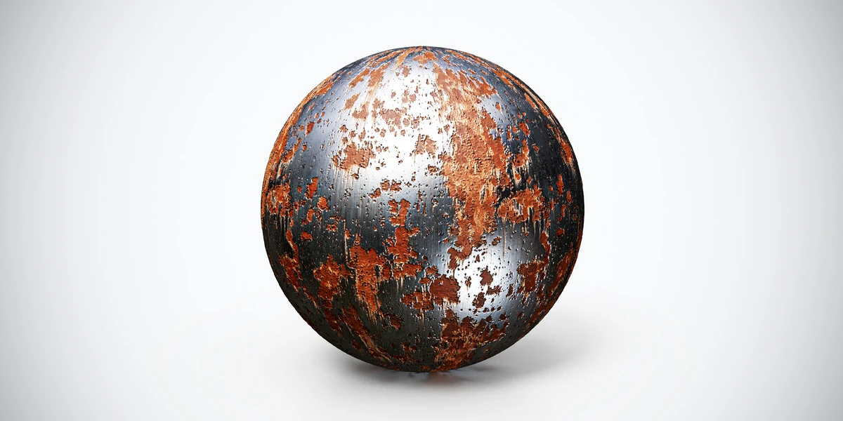
The rusted metal texture with orange patina provides a useful example with distinct corrosion and brighter exposed regions. Use its broad patches to evaluate material separation before adding extra dirt layers.
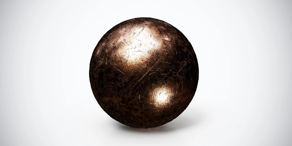
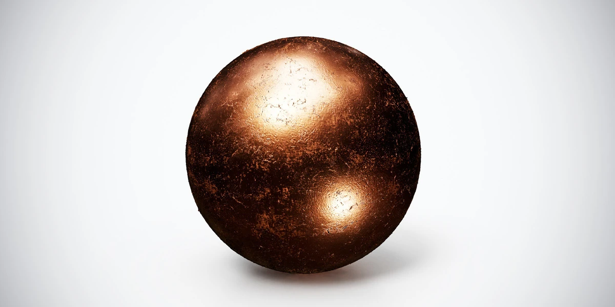
For comparison, scratched bronze emphasizes fine wear across darker warm metal. A copper metal material gives another reference for colored metallic reflections. These are different material choices, not substitutes for the chemistry or appearance of rusted iron.
Choose one main finish for the exercise. Keep the alternatives on copies of the same test object so geometry and lighting do not change with every material swap.
Build a panel that can reveal material problems
Create a rectangular panel with real thickness, modest edge bevels and a few simple fasteners. Establish its scene dimensions before unwrapping. A flat plane shows the image pattern, but a beveled object also reveals how reflections travel across the form.
Use a checker first. Avoid stretched UVs around corners, and keep comparable faces at consistent texture density. If the checker looks distorted, use the UV stretching diagnostic workflow before judging the rust pattern.
Place a neutral object beside the panel as a lighting reference. Save one frontal camera and one oblique camera. Do not add dramatic colored lights yet: their reflections can make it difficult to distinguish the metal’s intended color from the environment.
Connect the supplied maps without inventing extra channels
Use a Principled BSDF and inspect the files actually supplied with the material. For a conventional separate-map set, connect Base Color to Base Color, Roughness to Roughness and Metallic to Metallic. Interpret the color map as color and the numeric maps as data.
Feed the normal image through a Normal Map node before connecting it to the shader’s Normal input. The Blender Normal Map reference specifies Non-Color interpretation and matching UV coordinates for tangent-space maps. Check the supplied normal convention instead of changing light direction to disguise inverted detail.
Keep all image maps in the set on the same intended mapping path. Moving only the color image can put a rust-colored patch over the reflection response or relief of an unrelated region. The complete Blender PBR setup guide covers the basic node connections in more detail.
Leave Height disconnected for the first comparison. This makes it easier to judge material response before adding another source of surface variation. An AO image also deserves inspection; avoid aggressively darkening cavities that the scene already shades convincingly.
Read Metallic as a material mask, not a shininess control
In a metallic–roughness workflow, bare metal and rust should not receive the same material classification. Adobe’s PBR guide treats corrosion as dielectric, while exposed raw metal retains metallic behavior.
Inspect a few identifiable locations in the color and Metallic images. Does an orange corrosion patch correspond to a non-metallic region? Does the brighter exposed area retain metallic response? This is a consistency check, not a reason to threshold every gray edge in the supplied map. Filtered boundaries and unresolved mixtures can contain intermediate values.
Do not lower Metallic across the whole panel merely because the reflections seem too sharp. That changes material identity as well as appearance. Blender’s Principled BSDF documentation distinguishes the Metallic and Roughness inputs; diagnose them independently.
If a map does not agree with the material reference, make the correction deliberately and save a separate working version. Do not assume every dark pixel in Base Color is rust: it might represent dirt, a different surface feature or unwanted baked shading.
Set rust and scratch size against the object
Use panel seams, bolts and handles as visual rulers. A rust patch that works across a large storage door can cover an entire small bracket. Conversely, extremely fine scratches may become distracting noise when repeated over a broad wall.
Choose the texture coverage first, then inspect the crop on each important face. A recognizable orange island repeated at identical intervals can reveal the tiling even when the image edges join cleanly.
Add object-specific wear only where the object’s construction supports it. A rubbed handle area or streak beneath a fastener can explain use; arbitrary bright edges on every corner can make the same history appear everywhere. For a scene-level application, the workshop environment guide helps place worn surfaces within a coherent setting.
Compare roughness under fixed lighting
Keep the camera, exposure and object fixed while rotating the lighting environment. Inspect a clean metal region and a corroded region separately. The roughness-map guide explains why highlight shape provides information that a color-only view misses.
Use a broad light source to read the panel’s form, then a more concentrated reflection to inspect small wear. The HDRI product-lighting workflow provides a repeatable comparison scene.
| Symptom | Check first |
|---|---|
| The entire object resembles polished orange metal | Metallic classification across the corrosion |
| Bare metal looks almost black from one angle | What that region reflects in the environment |
| Every patch has the same sharp highlight | Roughness connection, interpretation and variation |
| Fine scratches dominate the whole object | Pattern scale and normal strength |
Change one variable between renders and keep the previous result. This prevents a lighting adjustment from hiding a map error that will return in another scene.
Reserve geometry for damage that changes the outline
Normal detail cannot create a torn edge or an actual hole through the panel. Model the damage that changes the silhouette, especially near the camera. Small pits can remain shading detail when that holds up in the intended view.
If you add height-based displacement, compare its result with the normal-only version and check border behavior. Blender’s displacement documentation distinguishes bump shading from actual mesh displacement, which requires suitable geometry. More displacement is not automatically a better representation of thin corrosion.
Finally, compare the available map sizes at the real viewing distance using the texture-resolution guide. Save the chosen coverage, channel setup and lighting baseline with the asset. When exploring other finishes in the metal PBR collection, reuse that baseline so the comparison answers a material question rather than rewarding the most dramatic preview.